Power Management


Power management allows for improved management of energy expenditures, increased safety and environmental effect mitigation.
It provides a highly integrated, high-performance architecture for a broad range of application categories, such as storage computing, networking, telecommunications, automotive, and consumer electronics. Today's systems require power supply design to be integrated with the system design in order to maintain high efficiency.
Power management ICs (PMIC) are employed for voltage conversion, voltage regulation and battery management. They are essentially a system-in-a-package solution. A single PMIC can manage multiple external power sources, supply power to multiple loads, and shield against unsupported overvoltage & under-voltage conditions, over-currents, and thermal faults. Less power consumption under varied load circumstances, less space, excellent dependability and a wide input voltage are some of the major needs of today's power management systems. In a wide range of applications, these criteria are driving the demand for highly efficient, wide VIN, low quiescent current (IQ) switching regulators.
Stay informed
Keep up to date on the latest information and exclusive offers!
Subscribe now
Thanks for subscribing
Well done! You are now part of an elite group who receive the latest info on products, technologies and applications straight to your inbox.
Building blocks of Power Management & Power Supply Design
Roll over the icon titles below for more information
Surge Protectors
Transformers
Test & Measurement
Power Supplies
Connectors-cables
Power Management
Battery management solutions
Power Supply
A power supply is an electrical device that provides electricity to a load. It broadly refers to the generation and control of regulated voltages required to operate an electronic system. The primary function of a power supply is to convert electric current from a source to the correct voltage, current, and frequency to power the load. The elements of power supply may include IC components such as switching regulators, linear voltage regulators, switched capacitor voltage converters, DC-DC Converters, AC-to-DC Solutions, PMIC -Power management IC, Battery Management, Power over Ethernet (PoE) and voltage references.
Some power supplies come as stand-alone units, whilst others are integrated into the load appliances that they power. They demand high stability and safety protection. Their uses span a wide range of product types, from consumer appliances to industrial utilities, milliwatts to megawatts, and portable tools to satellite communications. Industrial power supplies range in capacity from a few watts to many kilowatts and can be built to fulfil complex criteria such as convection cooling/no fans, ruggedised, conformal coated, or with IP Ratings for hostile environments.
Power supplies can limit the current drawn by the load to safe levels and shut off the current in the event of an electrical fault. They can perform power conditioning, to prevent electronic noise or voltage surges on the input from reaching the load. Perform power-factor correction, and store energy so that it can continue to power the load in the event of a temporary interruption in the power source. Since many electronic devices require different DC voltage levels, designers must develop a method to transform conventional power-source potentials into the voltages specified by the load. Voltage conversion must be flexible, efficient, and dependable.
Switch-mode power supplies are commonly utilised to supply the different levels of DC output power required for current applications, and they are critical in producing highly efficient, dependable DC-DC power-conversion systems. Buck, Boost, Buck-boost, Inverting, and Split rail are some of the most popular.
Power over Ethernet is a widely used technology that allows networked devices such as IP telephones, wireless LAN Access Points, security network cameras, and other IP-based terminals to receive power in parallel with data over existing CAT-5 Ethernet infrastructure without the need for a separate power supply. It minimises both the complexity and the risks associated with AC power processing. The latest update to the PoE standard is the IEEE 802.3at standard, often known as PoE+. These devices deliver maximum power output of 30 watts per port.
Wireless charging eliminates the need for cables to charge mobile phones, cordless appliances, and other wearable electronic devices. The wireless charging system comprises of a transmitter and receiver chip set that may be tailored for varied application needs and are compliant with the major wireless charging standards, including the Wireless Power Consortium's Qi (WPC). The battery in any battery-powered device may be charged with a wireless charger by simply placing the appliance near a wireless power transmitter or a certified charging station. The well-known Faraday's law of induced voltage is the basic concept used in wireless charging.
AC – DC
The power at the input can be either alternating current (AC) or direct current (DC). The electric current in AC periodically inverts its direction, whereas DC occurs when the current flows in one constant direction. DC is the preferred type of power for electronic devices. AC to DC Converters fall under the most significant in power electronics because they are used in many real-world applications where input is an AC voltage (50Hz/60Hz sine-wave) that requires power conversion to a DC output.
AC-DC converters can have multiple outputs and features such as overcurrent, overvoltage, and short circuit protection. To convert the supplied AC to pure DC, a typical AC to DC converter goes through four main steps. Step-Down the Supply Voltage; Rectify the Sinusoidal Wave; Smooth the Waveform to Minimize Ripples; and Regulate the Voltage to Produce the Final Output DC are the stages.
The process of converting alternating current to direct current is known as rectification. Rectifiers are built with semiconductor devices that exclusively conduct current in one direction, such as diodes. Thyristors are more advanced semiconductor rectifiers. Rectifiers are categorized based on factors like types of supply, bridge configuration and components used. It can be classified as single-phase and three-phase, based on the number of diodes used. It can be half-wave, full-wave or a bridge rectifier, and can also be controlled or an uncontrolled type. Uncontrolled Rectifiers Provide a fixed DC output voltage for a given AC supply. Controlled Rectifiers employ thyristors and diodes, which offer an adjustable DC output voltage by controlling the phase at which the devices are turned on.
The AC to DC conversion can be accomplished using Linear or Switching topologies. Linear type AC-DC converters are simple and affordable, but they are also bulky and inefficient. Excess power is converted as heat, which might be undesirable for some temperature-sensitive applications, but they have the advantage of generating low noise. Switching type AC-DC converters employ a switched-mode power conversion technique, they are more complicated compared to linear ones. The rationale for utilising more complicated topologies is generally to enhance efficiency, reduce noise, or function with superior power control.
For high energy efficiency, an AC/DC converter often requires excellent switching performance. This may be accomplished through the use of cutting-edge techniques and technologies such as silicon carbide (SiC), MOSFETs. To mitigate distortion and increase power factor, some switching converters include active or passive power factor correction. A switching regulator switches between full-on and full-off states relatively fast, minimizing wasted energy. Switching converters are more efficient, smaller, and lighter than linear converters, but they are also more complex. If not adequately suppressed, they can produce electrical noise problems, and simplistic designs may also have a low power factor.
AC-DC converter Power Supplies are available in a variety of package types and they can be an Enclosed Unit type, or an Open frame type, along with different options such as PCB mount, Rack mount, DIN rail, External etc, and are also available based on Peak Power Capability, or offer Simple Constant Current Control.
DC – DC
DC-DC converters are power supplies that convert a direct current (DC) voltage into various different DC voltage levels. They are a crucial component of almost all electronic circuits where different voltages are needed to power diverse circuit components. The input to a dc-dc converter is an unregulated dc voltage which is converted into a regulated dc output voltage.
It must function within defined DC parameters, such as the input voltage range, output voltage range, and maximum output current required for a certain application. Efficiency, output ripple, load control, transient responsiveness, temperature rating, size, and weight are some of the additional performance characteristics to consider. Another important element that impacts efficiency and noise is the switching frequency. Higher switching frequencies enable smaller external components, lower peak currents, and reduced I2R losses, but they also increase core losses, gate-charge currents, and switching losses.
DC-DC converters are classified into two types: linear and switched. While a linear DC/DC converter generates and regulates a certain output voltage through a resistive voltage drop, a switched-mode converts it by periodically storing the input energy and then releasing to the output at a variable voltage. Storage can be in a magnetic field component (Inductor, transformer) or an electric field component (capacitor). This conversion method can increase or decrease the voltage level. Linear regulators provide lower noise and higher bandwidth.
Switched-mode DC-DC is further classified into isolated and non-isolated converters. Isolated converters offer an input to output isolation barrier with the help of transformers and opto-couplers. This allows the output voltage to be floating and be used as a positive or negative polarity with respect to the system 0V. Isolated converters are useful for breaking up ground loops, thus separating parts of a circuit that are sensitive to noise. Safety requirements are a common reason to use an isolated DC-DC power converter. Isolation separates the output from dangerous voltages on the input and protects against electric shock or short circuit. High speed and high power applications employ isolated DC/DC converters.
When the voltage shift is minimal, non-isolated converters are employed. In this circuit, the input and output terminals share a common ground. A closed feedback loop is used to maintain constant voltage output with varying input voltages and output loads.
A switching DC/DC converter, also known as a regulator, is a circuit that transfers energy from the input to the output using a power switch, an inductor, a diode, and a capacitor. These can be combined in a number of ways to produce buck, boost, or buck-boost kinds. A buck converter generates a lower output voltage than the input voltage, and is termed a 'step-down' converter. Boost converter topology produces a higher voltage than the input voltage, and is also called a step-up converter. A Buck-Boost converter is a combination of buck and boost circuits, here converter output voltages can be higher or lower than the input voltage.
Switching converters with small and high power capacities have a wide range of applications, including power supplies, energy storage systems, energy transmission systems, electric vehicles, ship and train propulsion systems, renewable energy applications, and dc motor drives.
Charging
The power that comes from the grid is always alternating current (AC). When charging portable electronic equipment (such as cell phones and electric cars), electricity is converted from AC to direct current (DC). A Charging System is a device that transfers energy from a constant frequency, constant voltage supply network to direct current in order to charge the battery and operate electrical systems while connected.
In battery-powered systems, the charging circuit's quality has a significant impact on the battery's life and reliability. A good battery charger boosts capacity, increases battery life, and keeps track of the charging process. To tackle portable power conversion issues, a wide range of battery management solutions that support a number of battery chemistries are required. Battery charge management controllers are reliable, low-cost, and high-accuracy voltage regulation systems that need few external components, resulting in smaller, less expensive, and more sophisticated designs.
Portable applications demand both high conversion efficiency and low standby power consumption to sustain battery life. To maintain consistent power levels when the batteries drain, multi-cell battery packs may require step-down (buck) conversions, while single-cell batteries may require step-up (boost) conversions. Battery charging requires constant current or voltage regulation. These battery charging devices include features such as battery preconditioning, programmable charge currents, end-of-charge thresholds, and elapse timers, maximise fuel capacity and minimise charge time whilst maintaining battery life in low-component-count, small-area circuits which are ideal for portable applications.
Charging may be accomplished by conductive/wired charging, inductive/wireless charging, or by replacing the battery (swapping). Charging systems that employ the conductive/wired technique make direct contact between the connector and the charge inlet. A normal electrical socket or a charging station can power the cord. Conductive charging is preferred as it is considerably cheaper and more efficient.
Charging through inductive/wireless employs an electromagnetic field to transmit energy between two objects. This is generally accomplished with the aid of a charging station. Energy is transferred to an electrical device through an inductive coupling, which can subsequently use that energy to charge batteries or power the device. Induction chargers employ an induction coil within a charging base to generate an alternating electromagnetic field and a second induction coil in the portable device transforms the power from the electromagnetic field back into electric current to charge the battery.
Electric vehicles (EV) are powered by huge battery banks, constructed of extended strings of batteries in series. The Battery Pack is a collection of individual batteries that serve as the vehicle's primary fuel source. EV chargers are differentiated on the speed with which they recharge EV batteries. Optimal and safe use of these batteries require a BMS, which includes Battery monitor and control power storage systems, assuring the health of battery cells, and delivers power to vehicle systems. It accommodates a high voltage charger connector that connects the high voltage source to charge the battery within the vehicle.
There are several types of charging connectors, power management modules, power IC’s and Charging controllers, which can be used for a wide range of applications of conductive and inductive charging methods.
Battery Management
The rechargeable battery industry growth is driven by an increase in portable battery powered devices, electric vehicles, energy storage, and industrial applications. Various battery chemistries include lead-acid, nickel cadmium, nickel-metal-hydride, and lithium ion, and these require extremely accurate charging current and output voltages to meet the standards. To maintain the health of these cells in the battery pack and to deliver the power needed, a battery management system (BMS) is required. The Battery management portfolio includes Battery Authentication ICs, Battery Charger ICs, Battery Fuel Gauge ICs, Battery Protector ICs, and Battery Supervisor & Monitor ICs, which can be used for a wide range of applications.
A BMS is an electronic system that manages charging, discharge control and provides other advanced features like cell protection, cell monitoring & balancing, calculate battery life, controlling its environment, etc. The primary function of a BMS is to protect the battery and prevent any operation that exceeds its safety limit. It has several functional blocks, such as cut-off FETs, a fuel gauge monitor, a cell voltage monitor, a cell voltage balance, a real time clock, temperature monitors, and a state machine.
There are several types of battery management integrated circuits available. The functional components are organised in a variety of ways, ranging from a simple analog front-end (AFE) that provides balancing and monitoring to a system, which requires an active controller - a highly integrated system that operates autonomously. The microcontroller used in BMS measures cell voltage and current in real time and switches the MOSFETs accordingly.
In terms of hardware structure, centralised, distributed, and modular architectures are the three types of topologies implemented in a BMS. Several sensors are placed in the battery pack to collect data at the monitoring layer. The data acquired in real time is utilised to ensure the system's safety and to assess the battery's status.
Cell protection includes data acquisition of cell voltages, temperatures, and current. Data analysis determines the state of charge (SoC) and state of health (SoH) of the battery pack. It ensures control of external components to maintain cells within manufacturer recommended conditions (e.g. fans, heaters) and control of components to isolate the battery pack in the event of a cell failure (contactors).
Cell balancing provides a way to compensate for weaker cells by equalizing the charge on all cells in the battery pack to extend battery life. Two methods of cell balancing are often employed- Passive and Active cell balancing. In Passive, the bypass resistors are used to discharge excess voltage and equalise with other cells. In the active cell balancing, the excess charge of one cell is transferred to another cell with a low charge. It makes use of charge-storage capacitors and inductors.
Electric vehicles are powered by huge battery banks made up of long rows of batteries connected in series. The optimal and safe use of these batteries necessitates the employment of a BMS, which includes the ability to monitor and control power storage systems, as well as ensure the health of battery cells and supply power to vehicle systems.
Circuit Protection
Circuit protection is the intended use of a fail-safe device that causes a disruption in an electrical circuit when it senses an excess and unsafe load of power (either overcurrent or overvoltage conditions) in a circuit. An overload condition can be defined as the operation of equipment above its normal, full-load rating, or operating in excess of its rated capacity. Short-circuit currents (fault currents) usually occur with abnormally high current flow due to the failure of conductor insulation.
Fuses are current-sensitive devices designed with a piece of wire that readily melts when the current flow is too high and breaks the circuit. Resettable fuses, Cartridge fuses, and High breaking capacity fuses are types of fuses.
Fuses are circuit protection devices, which are available in a very diverse selection. This product line comprises of different types of circuit protection devices and associated products. Fuses, fuse clips, fuse holders, fuse blocks, circuit breakers, and positive temperature coefficient (PTC) resettable devices are examples of overcurrent products. Metal Oxide Varistors (MOVs), discrete transient voltage suppression diodes (TVS Diodes), thyristors, electrostatic discharge suppressors (ESD), and gas discharge tubes (GDTs) are examples of overvoltage products.
Zener diodes are one of the most commonly used circuit protection devices. If used in forward-biased mode, they will clamp voltages to around 0.6 V like any other silicon diode; however, when used in reverse bias mode they will clamp a voltage to a specific value.
Varistors are voltage sensitive devices that are used to safeguard circuits against transient voltage spikes. Multi-layer varistor (MLVs) are mainly surface mount devices with a ceramic multilayer-layer structure, these are intended to protect circuit boards in miniaturized electronics from transients caused by electrostatic discharge (ESD), inductive load, switching, and lightning surge transients. MOVs are zinc oxide discs encased in epoxy and may have radial or axial leads. MOVs are mid-range devices that are used to safeguard small machinery, power supplies, and components.
A transient surge is a sudden (shorter than a millisecond) rise in the flow of power. Transient surges result from a number of sources, the most common of which are internal, such as load switching and even normal equipment operations. These transients damage, degrade, or destroy electronic equipment. A surge protection device (SPD) is a component that reduces the quantum of harmful energy flowing into a system. SPD’s are the most common and well-organised type of over-voltage protective device. In the power supply circuit, the SPD device is typically placed in parallel with the power rails and can be utilised at any step of the power supply. SPD’s are primarily made using one or more of these types of technologies: Spark gaps or gas discharge tubes, MOVs, Zener Diodes, or Silicon Avalanche Diodes.
Circuit breakers, also known as MCBs are primarily mechanical and they function as an electrical switch that opens when an excessive current flows across a circuit. They can be reset without causing damage and a latching mechanism keeps the primary connections closed. They make electricity safer in everyday life.
Featured content
Ebook
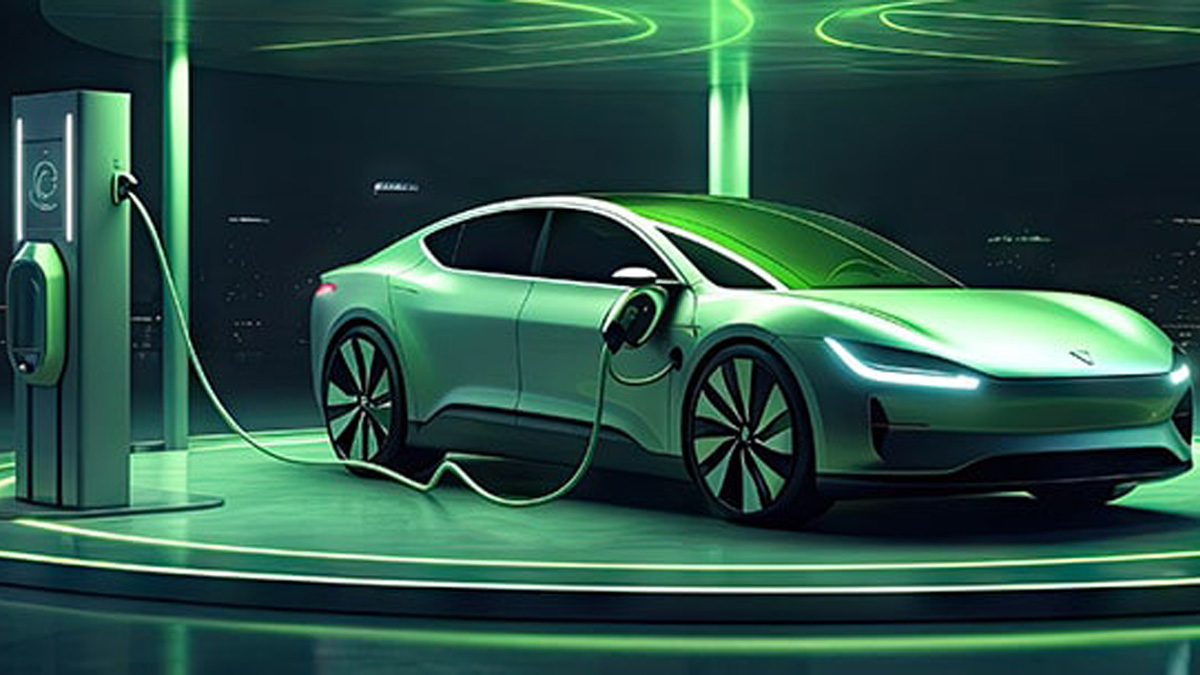
A Comprehensive Guide To EV Charging
Discover a top-notch resource for EV charger design! Our guide simplifies complex concepts, making it accessible for both beginners and experienced professionals to design efficient and reliable charging stations.
How to
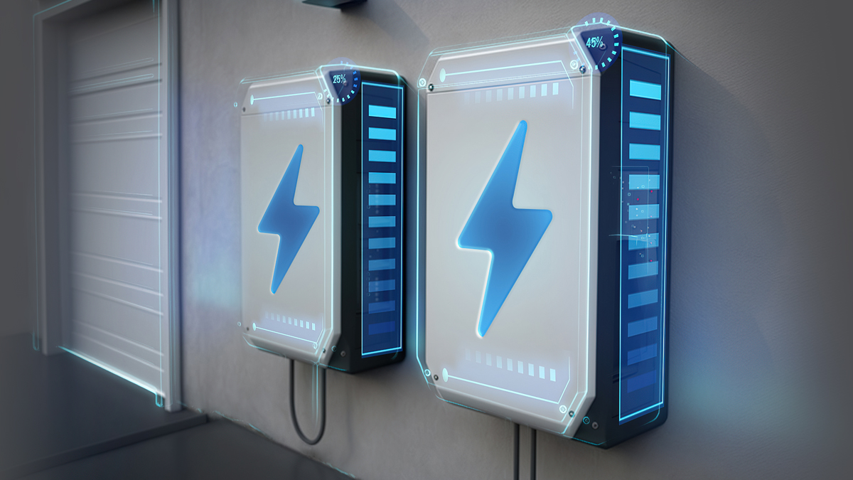
How Energy Storage System Evolution is Driven by Cell Chemistry and Control Electronics
Learn how energy storage system (ESS) progression, from smart watches to electric cars and renewable energy, improves performance, functionality, dependability, size, weight, cost, and energy consumption. Explore the complex relationship between battery cell chemistry and electrical management systems in ESS design.
How to
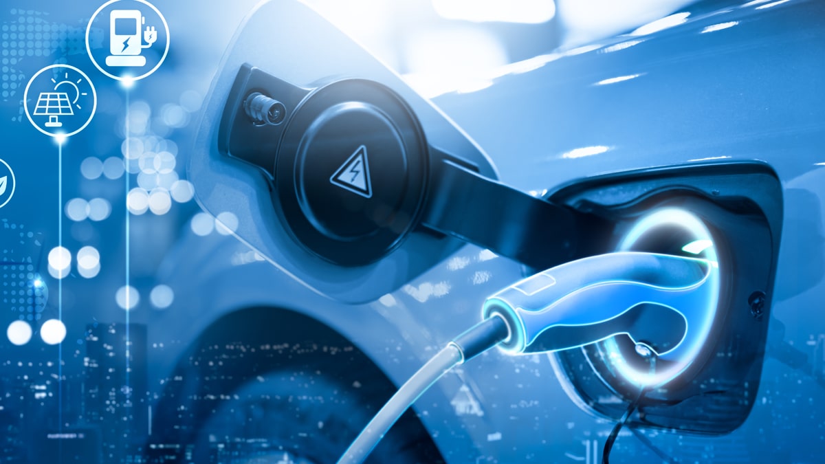
How to Design an Efficient Power Conversion Circuit for EV Chargers
This article will walk you through the intricacies of designing a power conversion circuit for EV chargers. A power converter is the primary link between the power source and the battery in EV charging.
Article
The Effects of Electric Vehicle Charging Stations to the Power Grid
This article discusses the impact of EV charging on power grid infrastructure and the possible solutions to mitigate the same to maintain its reliability and durability.